Tech808
Moderator
Username: Tech808
Post Number: 11610
Registered: 8-2002

| | Posted on Wednesday, October 18, 2006 - 12:04 pm: | 


|

RM ITALY
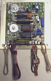
AD-203 Stinger Board

Connection Point's LEFT to RIGHT.
ANT ~ Power Supply ~ Power Switch ~ RTX

RM ITALY
AD-203 Stinger Board
Installation Instructions.
#1 ~ Remove speaker-side case of radio and remove speaker from the case.
(save the 4 screws and nuts).
#2 ~ The Radio will need to be Modified so it will only key 2-1/2 to 3 watts.
Super mod down or down tune for best results.
#3 ~ Locate the Antenna Jack (Ant) on back of radio and remove Antenna wire from the SO-239 jack. Locate the "RTX" Coax and "ANT" Coax on the AD-203 Amplifier.
The "ANT" coax will go to the jack and the "RTX" coax will be soldered to the wire which was removed from the SO-239 jack.
NOTE!
BOTH of the Shields on the RTX Coax & ANT Coax from the AD-203 board MUST be GROUNDED!
The hardest part of the Installation is separating the center strand from ther Shield on the RTX & ANT Coax from the AD-203'
HELPFUL TIP!
I very carefully cut the OUTER Clear Plastic on the RTX and ANT Coax from the AD-203 and used a fine dental Pick to pull the Center (also plastic coated) of the Coax OUT of the surounding Coax Shield.
The RED and BLACK power lead from the AD-203 Amplifier will be soldered to the radio power jack.
#4 ~ The RED and Black power lead from the AD-203 Amplifier will be soldered to the radio Power Jack. REPLACE the 3-amp fuse from radio with a 10amp fuse in the Power Cord.
#5 ~ The ON/OFF Switch can be mounted on the side or Top of Radio.
#6 ~ Mount the AD-203 Amplifier where the speaker was Removed.
#7 ~ On some radios ike the Cobra Sound Tracker radios a SHIELD will be needed on TOP of the MAIN Printed Circuit Board. This will keep RF out of the Audio Circuit.
NOTE!
A (RF SHIELD) Copper Board (2-1/2" x 3" is also furnished. Solder in on Top of the IF/RF Transformar.
#8 ~ Replace top case on the radio and replace the screws.
PLEASE NOTE!
The AD-203 Stinger Board will work on most SSB Radios but in some cases it may be neccessary to change the eletrolitic capacitor to allow for SSB delay.
DO NOT INSTALL IN ANY RADIO THAT WILL KEY MORE THAN (4) WATTS. per RM ITALY Installation Instruction's.
Respectfully Submitted,
Lon
Tech808
CEF808
N9CEF
CVC#2 |


