Tech808
Moderator
Username: Tech808
Post Number: 4091
Registered: 8-2002

| | Posted on Monday, November 15, 2004 - 4:40 pm: | 


|
MAGNUM 257  MODEL MODEL
This Review is good for models built after Mid-October, 2004
COPPER PART #P03-01000
AM/FM/SSB 10 METER MOBILE AMATEUR TRANSCEIVER
Complete Specifications, Modifications, and Non - Technical Review.
By
Lon ~ Tech808 ~ N9OSN
GENERAL SPECIFICATIONS:
| Frequency Coverage | 28.000 to 29.699 | | Frequency Coverage Expanded | 25.165 – 29.699 | | Antenna Impedance | 50 ohm unbalanced | | Frequency Control | Digital Phase-Lock Loop(PLL)Frequency Accuracy Better than +10ppm from 0-40° C after 15 min warm up. | | Power Requirment | 10.5 - 15VDC ~ Negative Ground | | Current Consumption | 6.0 amps maximum | | Dimensions | 6 x 2 x 9.5 in (WxHxD) | | Weight | 2.9 lbs. |
TRANSMITTER SPECIFICATIONS:
| Power Output | SSB / FM ~ 30 Watts AM ~ 9 Watts Average / 30 Watts PEP | | Tuning Steps | 1kHz / 10kHz / 100kHz | | Final Transistors | 2SC1969 (x2) | | Spurious Emissions | More than 50dB below peak output power | | Carrier Suppression | More than 40dB below peak output power | | FM Deviation | +/- 2kHz maximum | | Audio Response | More than 30dB below peak output power | | Frequency Response | 400 to 2800Hz | | Microphone Impedance | ECM 600 to 1K ohms |
RECEIVER SPECIFICATIONS:
| Circuit Type | Dual Conversion Superheterodyne | | Intermediate Frequencies | 1st IF / SSB IF ~ 10.695 MHZ ~ 2nd IF ~ 455 kHz | | Sensitivity | SSB 0.25 V at 10dB S + N/N / AM ~ 1.0uV at 10dB S + N/N / FM ~ 0.3 uV at 12dB SINAD | | Selectivity | AM/FM 6.0kHz (-6dB) / 18kHz (-60dB) / SSB 4.2kHz (-6dB) / 8.5 kHz (-60dB) | | Clarifier Range | +/- 1.5 kHz | | Adjacent Channel Rejection | Better than 70dB | | IF Rejection | Better than 80dB for all frequencies | | Frequency Response | 250 to 3000 Hz | | Audio Output Power | 2 watts minimum at 10% THD with an 8 ohm load | | Audio Output Impedance | 8 ohms |
FREQUENCY MODIFICATION:

Step #1: Make sure Magnun 257 is turned off and disconnected from power sourcel!
Step #2: Take off speaker-side cabinet.
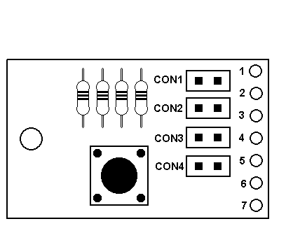
Step #3: Find the CPU Reset Board located near the Front panel of the radio located behind the Microphone Connector.
Step #4: On the CPU Reset Board there are 4 jumper positions (CON-1 / CON-2 / CON-3 / CON-4).
Each jumper position will provide a different frequency range and configuration.
From the list below, select the desired frequency range and configuration, and move the jumper shunt to the corresponding CON #.
CON1: ~ 10 Meter Only (28.000 - 29.699 MHz)
*Default mode
*All functions operate normally
CON2: ~ 10 Meter & Expanded Mode
*At turn on, the radio defaults to 10 Meter mode.
*For Expanded mode, press FUNC and then press CALL for 3 seconds.
*To return to 10 Meter mode, repeat above steps.
for information on Expanded mode operation, see CON3
CON3: ~ Expanded Mode Only (25.165 - 29.699 MHz)
In the Expanded mode, the frequency range is divided into 10 Bands of 40 Channels each.
The Bands are shown on LCD display by letters (A through J) - Band E is regular 40 channel CB. To switch bands, press the CALL button (do not hold down for 3 seconds).
In the Expanded mode, either the frequency or channel can be displayed on the LCD. To switch between freqency display and channel display, press the FUNC button and then press the CALL button (do not hold down for 3 seconds).
On the channel display, the small number (0 - 9) to the right of the Band letter is the 1 kHz frequency display.
Example: If the frequency is 27.405, then the channel display will indicate 40 E5. (40) being the channel, (E) being the Band, and (5) being the 1 kHz position of 27.405.
Note!
In the Expanded mode, the RPT and SHIFT functions Will Not Operate.
CON4: ~ 40 Channel CB Only (26.965 - 27.405 MHz) (Only operates on the regular 40 CB channels.)
Step #5 After selecting the desired frequency range and configuration, press the CPU Reset Switch (SW1) for 5 - 10 seconds.
Step #6 Reassemble the radio, turn on and test.
TUNE – UP / POWER TWEAKS
#1 ~ Remove bottom cover
#2 ~ Locate RV16. (AM Power)
#3 ~ Adjust RV16 for a carrier of 10 watts on AM mode with the RF Power knob turned fully clockwise. With the RF Power knob turned fully counter-clockwise, the AM carrier should be 1 watt.
#4 ~ Locate RV4. (Modulation)
Adjust RV4 for maximum modulation.
#5 ~ Locate RV9. (SSB Power)
Adjust RV9 for maximum forward power in SSB mode.
#6 ~ Locate RV8. (RF Meter)
With RF Output power knob adjusted to show a 5 watt carrier, adjust RV8 just until the 3rd RF power bar lights up.
You should now see a PEP output of around 25 Watts on AM and around 35 Watts on SSB. 
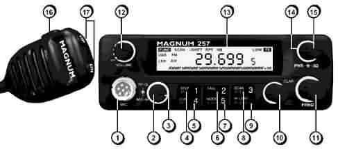
FRONT PANEL CONTROLS

#1 ~ MICROPHONE INPUT
Pin #1 ~ Microphone Audio / White
Pin #2 ~ Receive / Black
Pin #3 ~ Transmit / Red
Pin #4 ~ Down(Up w/22K Ohm Resistor) / Blue
Pin #5 ~ Ground / Shield w/yellow sleeve
Pin #6 ~ +13.8VDC / Brown
#2 ~ MIC GAIN
#3 ~ RF GAIN
#4 ~ STEP BUTTON \ NB \ 1 STEP
Controls tuning steps in either 1 kHz, 10 kHz, or 100 kHz as well as activates the Noise Blanker circuitry when used with the FUNCTION button. This button is also used to program and recall Memory Channel #1.
#5 ~ LCR \ RPT \ 4 LCR
Allows you to tune into the last channel you transmitted on. Also used to activate repeater splits when used in conjunction with the FUNCTION button. This button is also used to program and recall Memory Channel #4.
#6 ~ CALL \ 2
CALL The default call frequency is 29.300 MHz FM. Press this button to go to that frequency.
This button is also used to program and recall Memory Channel #2.
#7 ~ MODE \ T. LOW \ 5 MODE
Allows you to change the mode of transmission and receive AM/FM/USB/LSB. When using the FUNCTION button you can also activate the Tone Low circuitry which acts as a roll-off for high frequency or “white noise”. This button is also used to program and recall Memory Channel #5.
#8 ~ SCAN \ SHIFT \3 SCAN
Scans in increments 10 kHz steps. Also used to program repeater pairs\splits for FM repeater use. This button is also used to program and recall Memory Channel #3.
#9 ~ M. SAVE \ M. LOAD
Memory Save and Memory Load (Recall)
#10 ~ CLAR \ FUNC
Clarifier shifts both the TX and RX frequency 1.5 kHz each side of the center frequency.
#11 ~ FREQ
Rotate clockwise or counterclockwise to select desired frequency.
#12 ~ OFF \ VOLUME
Turns the power to the radio on and off.
#13 ~ NONE!
THE FACTORY FELT THE NUMBER 13 WAS UNLUCKY!
(You will not find a Number 13 listed in the Owners Manual)
#14 ~ SQ
Squelch, Used to elimate background or white noise and also used to activate the Scan feature (refer to #8.
#15 ~ PWR
Variable RF Output Power.
#16 ~ Push to Talk Switch (PTT) SWITCH
Push to talk, Release to receive.
#17 ~ UP \ DN
Allows for Up and Down Frequency Control from the Microphone.
OTHER FEATURES:
#1 ~ PROGRAMING TONE
This tone sounds each time the CPU is being programmed. It is helpful, in the beginning so you can be sure the command has been entered. You may eliminate the tone by simply pressing the PTT switch on the microphone and turning on the ON/OFF POWER switch at the same time.
#2 ~ MEMORY BACK UP
The 257 features a super-capacitor back up for the 5 memoery channels. The 257 can be disconnected from a power source for approximately 4 or 5 days before the memory is lost.
PROS & CONS
PROS
5 Memory Inputs can be stored in Memory and remembers the Frequency and Mode.
2 Separate Heat Sinks on back of Radio, 1 for the Transmit Finals and 1 for the 2SB754 Transmit Audio Amp.
Microphone Connector has (13.8 VDC) so Ham Radio Mics are easily adaptable.
Very Small Size (7-7/8 x 10-5/8 x 2-3/8) allows for easy mounting in most vehicles.
 CP1 SPEECH COMPRESSOR CP1 SPEECH COMPRESSOR
 BLUE Channel Display and LED Lights BLUE Channel Display and LED Lights
(No more bulbs to burn out!)
Good Tight Control Knobs
Excellent AM and SSB Modulation (NO Power Mic Needed.)
Very Stable on SSB with Excellent Audio Reports.
 Variable Power (Allows for use with Low Drive Amplifiers) Variable Power (Allows for use with Low Drive Amplifiers)
SMT Components
LCR (Last Channel Recall)
T.LOW FUNCTION (Rolls off High Frequency noise (ie: White Noise)
SCAN Feature
SHIFT Feature (Used for programming Repeater offsets)
Very Good and Easy to understand Owners Manual
Very Reasonable COPPER ELECTRONICS Price of $169.99
CONS
Only a 5 Digit Frequency Display a 6 Frequency Counter would be nice, (But in doing the Review it was Accurate.)
UP / DOWN Buttons need to be reversed on the Hand Mic)
REVIEW and COMMENTS
The MAGNUM 257 is the only radio that I had never used or even seen one until receiving one for this Review.
I was very pleased with the Small Size of this radio as in our new ford truck space is limited.
The small size of this redio is Great and will allow easy mounting in most vehicles.
I can honestly say I have been amazed with the Overall Performance / Quality and many features that this radio has to offer.
I cannot say how it compares to the Older version as I have never used one, but the  257 has exceptional performance and very good / clear modulation on both AM and SSB use. 257 has exceptional performance and very good / clear modulation on both AM and SSB use.
The NB and T.LOW feature works very well and came in very handy on the Sunday CEF nets.
Every Report I received on Modulation and clarity was 100% Loud and Claer with No distoration.
You do not need a power Microphone with this radio.
I also own an HR2510 and a new Lincoln and was very interestred in how it would match up / compare to these.
Hands down in side by side comparisons everyone picked the MAGNUM 257 over them both for clarity / audio and received signals on AM and SSB use.
This radio has surpassed every expectation that I had before receiving it and actually using it.
This is one of the Finest Quality built radios I have seen and used and I would highly recommend this  MAGNUM 257 for a First time user New to the hobby or a more experienced user. MAGNUM 257 for a First time user New to the hobby or a more experienced user.
Quality, Performance, Features, and Reasonable Price make the  MAGNUM 257 a Big Winner. MAGNUM 257 a Big Winner. 
NOTE UPDATED:
Friday, May 11, 2007 - 8:00 pm: !
There is no difference in Frequency Coverage or Conversion with the  ERF-2030 MOSFET powered models. ERF-2030 MOSFET powered models.
Respectfully Submitted,
Lon
Tech808
N9OSN
|


