| Author |
Message |
    
Twentynineva
Junior Member
Username: Twentynineva
Post Number: 19
Registered: 5-2010
| | Posted on Sunday, August 15, 2010 - 7:21 pm: | 


|
Well,i'm thinking about upgrading. Currently im running a Maco m103, and wondering how much difference the 5 element would make. If its not alot, then i wont think about it. Thanks |
    
Mikefromms
Senior Member
Username: Mikefromms
Post Number: 1044
Registered: 6-2003
| | Posted on Sunday, August 15, 2010 - 9:06 pm: | 


|
I believe you will add about 2 dbd gain for each additional element up to 5 elements then I believe it drops to about 1 dbd for each element after 5 elements. If it's not too much trouble to put up, give it a try. |
    
Starface
Senior Member
Username: Starface
Post Number: 2885
Registered: 1-2005

| | Posted on Sunday, August 15, 2010 - 11:55 pm: | 


|
Maco M-103C 3 Element Beam
Maco is one of the most trusted and respected names in base station antennas. The Maco 103c is a 3 element cb base antenna which has a wind survivability rating of roughly 90mph.
Features
* 3 Element/ 11 Meter Base Antenna
* "Maximum Beam", Gain: 11(db)
* Adjustable Gamma Match
* Boom Length: 11.5', Turn Radius: 10'
* Power Multiplication:20x
* Front to Back Seperation:25(db)
* Stack with YQSK for extra 3db
* Boom OD (inches) 1.5
* Longest Elements (ft) 19
* Surface Radius (sq. ft.) 4.5
* Wind Survival (mph) 90
* Tuning (Meters) 10-11
* VSWR (adjustable) 1.5 or less
* Weight (lbs) 14
Maco M105C 5 Element Beam
Features
* 5 Element/ 11 Meter Base Antenna
* "Maximum Beam", Boom Length: 26'
* Adjustable Gamma Match
* Gain: 15.5(db), Turn Radius: 15'
* Power Multiplication: 40x
* Front to Back Seperation: 31db
* Stack with MBSK for extra 3db
* Boom OD (inches) 2
* Longest Elements (ft) 19
* Surface Radius (sq. ft.) 8.47
* Wind Survival (mph) 90
* Tuning (Meters) 10-11
* VSWR (adjustable) 1.5
* Weight (lbs) 35
You will gain 4.5 (db)over the Maco m103
Life is a mirror and will reflect back to the thinker what he thinks into it.
|
    
Tech833
Moderator
Username: Tech833
Post Number: 1846
Registered: 8-2002
| | Posted on Monday, August 16, 2010 - 11:49 am: | 


|
Doubling the number of elements adds 3 dB.
For instance, a typical 3 element yagi has 9 dB gain. A 6 element yagi has 12 dB gain.
Yes, I know what the CB antennas makers say their beam antenna gain is, but that simply isn't any more true than an Antron 99 having "9.9 dB gain", as they advertise.
Your radio 'Mythbuster' since 1998
|
    
Twentynineva
Junior Member
Username: Twentynineva
Post Number: 20
Registered: 5-2010
| | Posted on Monday, August 16, 2010 - 12:20 pm: | 


|
How much real world difference will this make,mainly for dx. Think its worth the money to upgrade? |
    
Mikefromms
Senior Member
Username: Mikefromms
Post Number: 1045
Registered: 6-2003
| | Posted on Monday, August 16, 2010 - 5:54 pm: | 


|
The flat side at about 18 foot off the ground should be perfect for dx. At exactly a half-wave on 11 meters 17 or 18 feet, the your pattern is just about perfect for dx. I had some older friends back some years ago and they ran their big sticks and PDL II's low like that and worked the best dx.
I think there is a point of diminishing returns when the beam gets so big it becomes expensive, hard to handle, hard to turn, must have expensive rotor forth. However, that said, it's you that must be happy. If you only wanted or needed to be 17 feet off the ground at the feedpoint then I guess it wouldn't be near as much trouble putting a 7 or 8 element up there as up on a 75 foot tower. Knowing what I know now, I will never own another tower over 50 feet high.
I agree with the Tech833 on the gain. I believe diminshing returns begins after 5 elements. Not enough different to compensate for the extra expense to hold it up. But if I no one objects and you love this hobby this much go as big as your heart desires. You only go around here once. 73's. |
    
Tech833
Moderator
Username: Tech833
Post Number: 1847
Registered: 8-2002
| | Posted on Tuesday, August 17, 2010 - 1:02 am: | 


|
Mike is right. 5 elements seems to be about the breaking point.
If all you care about is your transmitted signal, read this- 3 dB gain about 1/2 of an S-unit on the receiver's meter. If you ran a 3 element beam, then switched to a 6 element beam, with everything else being the same, and communicating groundwave (not DX or 'skip'), you would have one half lousy S-unit increase in signal to whomever you were talking to. Go to a 12 element beam and you get one whole S-unit. Etc.
But in order to truly answer your question, we have to get a little technical.
This pertains to horizontal polarized beams mostly- A 3 element beam has a fairly wide beamwidth. Assume your 3 element beam is about 20 feet off the ground (to the boom). Your takeoff angle is about 16 degrees from horizontal, but with a nice wide beamwidth, so whether stations are 500 miles or 1500 miles away, they all hear you just fine (assuming proper refraction angles from F or E layer as the case may be). Go with the 6 element beam, and your beamwidth is much more narrow. So, assuming same height etc., the 16 degree takeoff angle is ideal for 1000 mile contacts (estimate) but becomes less ideal for stations closer and further than that distance. A station with a 3 element beam next door to you would kick your signal off the dial to a station 1500 miles away, but you would kick his off the air at 1000 miles. For 11m DX, a low takeoff angle is crucial, but the wider beamwidth is somewhat of an advantage for overall communications with distant stations of unknown distance and ionospheric conditions.
Some highly directional rotatable commercial SW antennas (usually log periodics), and a few hams use rotors to change horizontal direction and motors to change elevation angle as well. This way, they can use a higher gain antenna and still be able to hit the ionosphere with optimal angle for the distance they want the signal to travel.
Since multiple rotors to change horizontal AND vertical orientation is expensive, and clumsy, most hams and commercial SW stations using beams choose one with LESS gain (fewer elements) so that the elevation angle isn't critical.
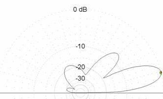
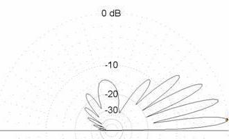
See below. Modeling over ground is much different than in free-space. First is a 3 element beam at 20 feet AGL, second is a 6 element beam at 20 feet AGL (same mast, coax, etc.) Assuming the critical angle for a certain contact is 5 degrees, the 6 element beam at 20 feet AGL has the advantage. Assuming the critical angle is anywhere from 10 to 20 degrees, the 3 element clearly has the advantage. The 6 element shows NEGATIVE gain (a minima) at critical angle of 12 degrees.
 
So, what is the advantage of more elements? Greater directivity and interference rejection in your receiver. A bigger beam buys you a better, quieter receive with more signals, especially when you need to hear a signal through the noise.
Your radio 'Mythbuster' since 1998
|
    
Starface
Senior Member
Username: Starface
Post Number: 2886
Registered: 1-2005

| | Posted on Tuesday, August 17, 2010 - 2:07 am: | 


|
Ah the good old Smith charts... Got to love them..
Life is a mirror and will reflect back to the thinker what he thinks into it.
|
    
Twentynineva
Junior Member
Username: Twentynineva
Post Number: 21
Registered: 5-2010
| | Posted on Tuesday, August 17, 2010 - 9:51 am: | 


|
Thanks a Ton for the info!! |
    
Tech833
Moderator
Username: Tech833
Post Number: 1847
Registered: 8-2002
| | Posted on Saturday, August 21, 2010 - 12:44 am: | 


|
Smith charts? I didn't use any Smith charts here. A Smith chart is for calculating the feedpoint resistance and reactance to determine rotation and bandwidth.
What I presented here is a computer simulation of what the radiated RF field would look like over average ground with beams mounted 20 feet above ground. Not even close to Smith calculations, but instead a complex algorithm of refraction and reflection and absorption, and the effect on currents and E/M fields.
Your radio 'Mythbuster' since 1998
|
    
Mikefromms
Senior Member
Username: Mikefromms
Post Number: 1046
Registered: 6-2003
| | Posted on Saturday, August 21, 2010 - 10:05 am: | 


|
Make that pattern as perfect as can be by getting in that 1/2 wave height and using a quality 1:1 balun. After some serious study, I'm about convinced a balun needs to be added to all groundplanes and beams that use coax. This might be the little secret that can aid in dx along with getting the flattop at the 1/2 wavelength above ground. |
    
Tech833
Moderator
Username: Tech833
Post Number: 1848
Registered: 8-2002
| | Posted on Saturday, August 21, 2010 - 1:38 pm: | 


|
Not exactly...
For HF beams, the higher the better. Forget the 1/2 wave theories.
For DX, a lower takeoff angle gets you out further. To lower your takeoff angle, you need to get your antenna higher above ground. A 3 element yagi at 50 feet will do much better than a 6 element yagi at 20 feet when it comes to DX.
A 1:1 balun is helpful for dipoles to keep the feedline from becoming part of the antenna. For a gamma fed yagi, the balun does nothing. Just one more thing that can go wrong waaaaay up there where it is difficult to reach.
Your radio 'Mythbuster' since 1998
|
    
Mrclean
Intermediate Member
Username: Mrclean
Post Number: 135
Registered: 12-2003
| | Posted on Sunday, August 29, 2010 - 3:09 pm: | 


|
I put up a Maco 5 element H/V at 58 ft to the boom and could not be happier. Was told that if you get a yagi over a wave and a half or higher thats as low of takeoff as your going to get. That would be 52 ft or higher. I dont have a groundplane up and it does have a fairly tight back and side rejection but not so tight that you cant hear alittle around you. Talks great and with about 500 avg 1600 pep or so DX and surface wave is so much better than the groundplane I ran before. What really impresses me is surface wave on the flat with someone on the flat on the other end. Many 150 mile plus contacts and 3 as far as 215 miles. Using a free standing Delhi tower and a yeasu g800sa rotator. Talked to a 5 pill mobile yesterday at over 100 miles on a distance calulator I use. I wanted something I could keep in the air and still get out the and talk and I think I made a wise choice.Check out this distance calculator. Its line of site and very handy.
http://www.distancefromto.net |


